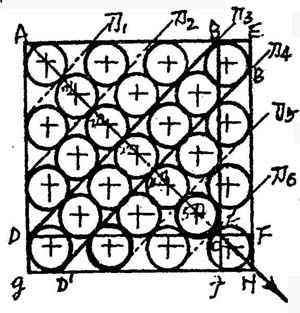
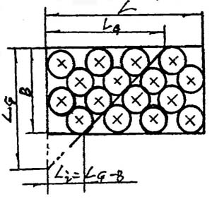
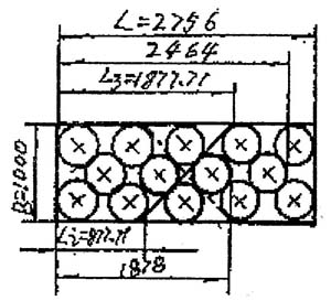
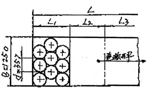
Cutting and calculation of circular blank layout plate (2) Li Guixiang 2, step by step cutting method for the calculation of the size If it is required to divide the layout plate in two steps, it is necessary to determine the slitting size when slitting the first knife, and to cut each of the entire batch of plates to be slit after the first knife is cut. In order to adjust the distance between the tailgate and the lower cutting edge of the shearing machine as the fixed number D in the single row slitting, or the fixed number ND in the multi-row slitting, the slitting is divided again in the new order. You can cut through the different layout plates. However, the ray directions made by the same apex angle of the same type of arranging plate are sequentially used as the sequence number, and the first knives in the order may be selected as the knives 1, the knives 2, .... It is possible to cut a knife in the end of the knife. However, it must be understood that this optional first knife may not necessarily be the best or preferred slit position relative to the layout plate. The determination of the optimal or preferred slitting position is generally based on the calculation of the specific conditions of the nesting, and is not obtained by an optional method. Because optional means that it can be determined according to the diameter of the layout within a certain range. The selection of the best or preferred cutting position must be closely related to the shape, size and diameter of the layout plate, and must be calculated to obtain a reasonable determination. However, there are some inevitable links between the choice and the special selection. When discussing the calculation of the optional and special cut size, this point must be taken into account. In order to accurately provide the best or better choice of the calculation, measurement, positioning and slitting properties of the slitting dimensions when selecting or selecting a particular knife. Whether it is the sequential selection or the slitting size of each knife or a certain knife in the order of the sequential selection, the following formula can be used for calculation. Lxn={[2+(2xn-1)√2]/2}d=[1+(xn-0.5)√2]d In the formula, when N=l, X may take 1, 2, .... N for all integers. That is, the following formula: Ln=[1+(n-0.5)√2]d; L2n=[1+(2n-0.5)√2]d;...... Lxn=[1+(xn-0.5)√2]d In the above formula, when n is equal to 1, it indicates that the formula is used for the calculation of the slitting size when single-row slitting; when n is an integer greater than 1, it indicates that the formula is used for the multi-row slitting of more than 2 rows. Cut size calculation. As shown in Figure 3. Figure 3 Schematic diagram of multi-row slitting size calculation It is easy to know from the analysis of the nature of the cutting position in Fig. 3 that any calculation of the multi-row slitting size can be converted into a single-row slitting size calculation method. Therefore, according to the general calculation routine, the calculation formula within the 10th knife of the single row slitting and the constant value to be obtained should be given, so as to calculate the slitting size. In the above calculation formula, when n=l is taken, when X is equal to an integer of 1 to 10, the calculation method of the following set of calculation formulas or their corresponding constant calculation values ​​can be obtained, so as to be used when calculating the slitting size. Calculate the formula according to the single-row slitting size that may be implemented with an optional knife: LG=BG=[(2+2G-1)/2]d You can get the formula or constant value for each slit size within 1 to 10 knives: L1=B1=[(2+√2)/2]d=1.70711d; L2=B2=[(2+3√2)/2]d=3.12132d;...... L3=B3=[(2+5√2)/2]d=4.53553d L4=B4=[(2+7√2)/2]d=5.94975d The following constant calculation formula can be obtained by analogy: L5=B5=7.36396d L6=B6=8.77818d L7=B7=10.19239d L8=B8=11.6066d L9=B9=13.02082d L10=B10=14.43503d According to the slitting size calculation of the above-mentioned sequential cutter positions, the calculation of the optional slitting size of the double equidistant staggered layout template is usually only related to the diameter of the layout, and is independent of the size of the layout plate. 3. Calculation of the best or better cut size by step-cutting method: In the step-cutting work, sometimes in order to improve the cutting precision and facilitate the slitting operation, the first knife of the slitting needs to be set at the optimal or better cutting position, so that the specification plate is divided into two parts. After the portion, the slitting is performed again to obtain the desired slitting effect. (The so-called optimal or preferred slitting position refers to the calculation and determination of the slitting size through the optimal or preferred slitting position with respect to the given plate and row diameter, so that the cutting plate can be optimally or The preferred position is divided into two portions that are symmetrical or nearly symmetrical, and the obtained slitting position is reached at the slit position at the longest position on the plate, which is called the best or better slitting position. Given the side of a corner of a layout plate as a reference, the positional size of the determined optimal or preferred slitting position can be calculated, referred to as the best or preferred slitting dimension. According to the above definition, the direction of the ray of the optimal slitting position line relative to an angle of the arranging plate is sequentially used as the sequence number, and there is only one single item, and the other apex angle is the reference. In other words, there is another one that is perpendicular to each other. That is to say, for the same layout plate, there are at most two optimal slitting positions with different directions. The preferred slitting position line can be at most two with respect to a certain angle, and at least one is still at least one, and the other adjacent apex angle is a reference, and the other two are perpendicular to each other. At the least, there is still another article perpendicular to it. That is to say, with respect to the same layout plate, there are at most four preferred slitting positions with different directions, and at least there are only two preferred slitting positions with different directions. As shown in Figure 4. In the parallelogram ABCD, BD is the only one of the best slitting position lines with respect to the same order direction of the AC, and the other vertex angle with respect to the angle is the sequential reference, and there are two perpendicular to each other. The strip preferably cuts the position line without the optimal slitting position line; in the parallelogram AEHIG, both BD and B'D' are two preferred slitting position lines relative to the same sequential direction of the AC, and The other apex angle of the adjoining corner is a sequential reference, and there are two other preferred cutting position lines perpendicular to each other, that is, there are at most four preferred cutting positions on the arranging plate; In the quadrilateral AEFD and the parallelogram ABJG, BD is the only one of the preferred slitting position lines with respect to the same sequential direction of the AC, and the other vertex of the adjacent angle is the sequential reference, and there is mutual Another preferred slitting position line in the vertical direction, that is, on each of the two types of boards, there are at most two preferred slitting positions, because the two boards obtained after slitting along the BD can only Is close to the basic symmetry and asymmetry, so it is called the better cutting position Can not say best cutting bit hood. The main reason for this phenomenon is due to the difference in the number of rows arranged along the diameter of the row in the row of the double equidistant staggered arrangement. Therefore, in practical applications, the choice is unique for the case where there is an optimum slitting position and only one preferred slitting position line. In the case of two preferred slitting position lines, the choice is for recording, and the general requirements are not very strict, and it is feasible to select which one is used as the slitting position line when performing slitting. It should be understood that there are similar equal or unequal slitting positions relative to the order of the same plate. However, the specific determination of each different cutting position perpendicular to each other must be determined according to the specific layout conditions, and can not be simply determined based on the fact that they are perpendicular to each other. Otherwise, it is easy to get a wrong conclusion that does not meet the actual layout. Figure 4 Schematic diagram of the solution of the square best or better cutting position and the corresponding cutting size From the previous discussion of the calculation problem, it is known that the calculation of any slitting size is related to the number of the cutter positions corresponding to each other, and once the corresponding number of the cutter positions is obtained. Then, the corresponding slitting size is easy to find. The calculation of the number of tool positions can be understood from FIG. Under the whole problem of the rounding algorithm, the 1/2 of the sum of d√2 along the length of the board and the width of the board is exactly equal to the number of the corresponding number of the best or better cuts. According to this truth: When the double equidistant misalignment scheme is implemented on the square layout plate, and the slitting is performed by the stepwise slitting method, the number of the cutter positions corresponding to the optimum or better slitting size can be calculated as follows: G=[2L(B)-2d]/2d√2=[L(B)-2d]/d√2 When the double equidistant misalignment scheme is implemented on the rectangular layout plate, and the slitting is performed by the stepwise slitting method, the number of the cutter position corresponding to the optimum or better slitting size can be calculated as follows: G=[L+B-2d]/3d√2 When calculating the number of tool positions corresponding to the best or better cutting position, the following points must be grasped, regardless of the integer part of the values ​​of L(B)-d/d√2 and L+B-2d2/d√2 Odd numbers are also even numbers, and all have the following properties: (1) When the fractional part is equal to or greater than 0.5, take the integer part plus 1 as the number of the location number corresponding to the optimal cutting position, and use it to participate in the corresponding optimal cutting ruler\j. When calculating, it is easy to get the correct calculation result. (2) When the fractional part is less than 0.5, the number of the number of the tool is corresponding to the JJ cutting position corresponding to the preferred cutting position, and is used to participate in the corresponding preferred cutting size calculation. Correct calculation results. From the above discussion, it is known that after obtaining the best or better tool position number, the corresponding optimal or better slitting size can be obtained separately according to the different shape of the layout plate: (1) When a double equidistant misalignment scheme is implemented on a square plate, and slitting is performed by a stepwise slitting method. The cut size corresponding to the best or better cut position can be calculated as follows: LG=BG=[1+(G-0.5)√2)]d In the formula, LG=BG respectively indicates the slitting size of the best or better slitting position on the square plate corresponding to different plate directions, and the unit is mm: G—— indicates the number of the tool position corresponding to the best or better cutting position, G=[L(B)-d]/d√2, the unit is; L (B) - indicates the side length of the square plate, the unit is mm; D—— indicates the diameter of the layout, the unit is mm. Example 2: The small opening of the steel drum with a diameter of 136 mm should be arranged on a slitting plate of 1005×1005×0.5 mm according to the method of double equidistant misalignment. Q. Is there an optimal or better cutting position when performing the slitting of the layout plate in the step-by-step cutting method? What is the number of slitting cutters in order? What is the corresponding slitting size? Solution: L(B) = 1005mm is known; d = 136mm; the number of tool positions G corresponding to the best or better cutting position and the cutting dimensions LG and BG are: Because the double equidistant row scheme is implemented on the square layout plate, and the slitting of the layout plate is performed according to the requirements of the stepwise slitting method. Therefore, whether there is an optimal or better cutting position must be solved to know. However, the number of tool positions corresponding to the best or better cut position can be calculated as follows: G=[L(B)-d]/d√2=(1005-136)/136√2=4.518 (knife) Since the fractional part 0.518 is greater than 0.5, it is known from the calculation point of the number of the tool position corresponding to the best or better cutting position that G=4+1=5JJ should be taken as the JJ position number corresponding to the optimal cutting position. number. Therefore, it can be judged that the optimum slitting position is the fifth knife which is arranged in order near the top of one corner of the plate. After obtaining the number of tool positions corresponding to the optimum cutting position, the optimal cutting position size for different plate directions can be calculated as follows: LG=BG=[1+(G-0.5)√2]d=[1+(5-0.5)√2]×136=1001.4986mm The experience of taking the whole LG=1002mm is about to cut from the diagonal position of the square plate to the best cutting position. That is, only the best slitting position without the preferred slitting position, the optimum slitting position, the j) bit number is the fifth knife; the corresponding optimal slitting size is L5=B5 is 1002 mm. (2) When the double equidistant misalignment scheme is implemented on the rectangular plate, and the slitting is performed by the stepwise slitting method. The best or better cut size can be discussed as such. As shown in Figure 5. When L≠B, the general case is L>B, that is, LG>Bg. In order to make the best or better slitting position ruler the longest possible, it is easy to obtain a higher cutting positioning accuracy. The best or better slitting size LG can be taken on one of the long sides of the board with a wide side of the board, and a point a is obtained: the corresponding best or better cut is taken on the other long side of the board. The size Li = LG-B, and another point b is obtained. The straight line connecting a and b points is the best or better cutting position line. Then, according to the single-row or multi-row slitting method, after the shearing machine is adjusted differently, the whole part of the cutting board can be cut. Figure 5 Schematic diagram of the solution of the best or better cutting position of the rectangle and the corresponding cutting size After obtaining the best or better cutting tool number, the corresponding best or better cutting size can be obtained by the following two formulas: LG=1+[(G-0.5√2)]d Li=LG-B Where LG, Li - respectively represent the best or better slitting dimension, calculated in terms of the same broad side, in mm: G - indicates the number of digits corresponding to the best or better slitting position, G = L + B - 2d / 2d √ 2, in units; L, B - respectively represent the length and width of the rectangular plate, the unit is mm; D—— indicates the diameter of the layout, the unit is mm. Example 3: The double-equivalent misalignment method is adopted, and the top (bottom) of the steel drum with the diameter of 414 mm is arranged on the 1000° wide coil cutting plate for the purpose of obtaining a relatively high layout. rate. And the plan is to cut the board into a certain length of the board with the best cutting position, and then transport the board to a barrel factory for cutting again to cut the board which can be cut in the blanking. Forming. When the length of the opening shear is asked, can it be the layout plate with the best cutting position, and find the corresponding optimal cutting tool number number as the first knife? What is the corresponding slitting size? Figure 6 example analysis diagram Solution: As shown in Fig. 6, the known plate width B = 1000 mm; the straight line d = 414 mm; the unwinding length L of the coil. The reasonable value of the J-digit number G of the double equidistant staggered scheme and the corresponding slitting dimensions LG and Li. 1. Because the board length L which is generally convenient for packing transportation and slitting operation is about 2000mm, it is appropriate. Therefore, the initial board length is L1=(2.5√2+1)×414=1878mm L2=(3√2+1)×414=2771mm L3=(3.5√2+1)×414=2464mm L4=(4√2+1)×414=2756mm 2. Calculate the values ​​of L1, L2, L3, and L4 respectively, and analyze whether there is the best number of cutting force numbers and the corresponding length of the slitting length: G1=(1000+1878-2×414)/2×414√2=1.75 Because the fractional part of Gl is 0.75 greater than 0.5, when G=G1=1+1=2, the number of the location corresponding to the optimal slitting position is obtained, and there is a corresponding optimal slitting size L2 and Li=. L2-1000 corresponds to it. As shown in Figure 6. Due to the double-empty phenomenon in the single row at the right end of the row, the layout utilization rate is higher than that of the positive row scheme, but it is low compared to the superior double equidistant misalignment scheme. Therefore, it is not advisable to use the layout scheme with the best slitting position under this condition. G2=(1000+2171-2×414)/2×414√2=2.0009 G3=(1000+2464-2×414)/2×414√2=2.25 Since the fractional parts of G2 and G3 are both less than 0.5 and 0.25, when G=G2=G3=2, only the preferred cutting position and no optimal cutting position are available, so it should be discarded. G4=(1000+2756-2×414)/2×414√2=2.509 Since the fractional part of G4 is 0.509 greater than 0.5, when G=G4=2+1=3 knives is taken, it is the number of tool positions corresponding to the optimum cutting position, and the optimal cutting position corresponds to it. 3. After solving, it can be determined that when the third cutting position is taken as the best cutting position, the corresponding cutting size can be calculated as follows: L3=[1+(3-0.5√2)]×414=1877.71mm Li=1877.71-1000=87.771mm That is, when the cut length is 2756 mm, it can be a reasonable layout plate with the best slitting position. As shown in Figure 6. And the corresponding optimal cutting tool number is the third knife in sequence; the corresponding slitting dimensions are L3=1877.71mm and Li=87.771mm respectively. (3) Cutting calculation of the unidirectional misalignment plan layout plate The slitting method of the unidirectional staggered layout plate is a relatively complicated one of the cutting methods of all the circular blanks. In the case of a certain misalignment, the amount of misalignment or the amount of misalignment is different. The calculation of the size of the centroid is ever-changing, and it is difficult to find a unified calculation law. However, it is not necessary to study the amount of misalignment relative to the possibility of slitting in the actual layout plate. From 0 to d/2, or between the corresponding rows and rows, the misalignment angle varies from 0-30°. That would make the slitting calculation of the one-way staggered layout board more complicated and complicated. In essence, it is the case that there is a possibility that the displacement is equal to d/2 or the misalignment is 300. As shown in Figure 7. Because the row spacing on the layout plate obtained in this case is the smallest, the layout utilization is relatively high. There is a need to discuss the need for cut calculations. In other cases, the unidirectional staggered layout of the splicing plate can be more specifically solved by a similar method. For details, please refer to the article "Implementation of the Misplacement Method" in the fourth issue of the "Steel Barrel" magazine in 1999. It is not repeated here. Figure 7 Schematic diagram of the unidirectional staggered board slitting calculation When the misalignment amount is d/2, that is, the unidirectional staggering scheme when the misalignment inclination angle is 30°, the slitting size calculation of the layout plate should be considered as follows in the following two cases: 1. When the diameter of the layout is large, in order to facilitate the punching operation, it is often common to divide the layout plate into double rows. Relative to the plate orientation, there are only two basic cases of slitting and crosscutting. The slitting width at the time of slitting is B1, B2, ... Bn is exactly equal to the slitting widths L1, L2, ... Ln at the time of crosscutting, and is equal to the sum of one row diameter and one row. That is, the slit size width can be calculated as follows: L1=B1=L2=B2...Ln=Bn= (l+√3/2)d Where L1, Bl, L2.B2... Ln and Bn respectively indicate the width of the slitting dimension corresponding to the length of the plate or the width of the plate, and the unit is mm; D—— indicates the diameter of the layout, the unit is mm. 2. When the diameter of the layout is small, under the whole problem of convenient punching operation, the layout plate is cut into two rows and more rows of slitting plates, which are directly sent into the upper and lower die for die-cutting. There are only two basic cases of slitting and die cutting in relation to the orientation of the plate. The slitting width at the time of slitting is B1, B2, ... Bn is exactly equal to the slitting widths L1, L2, ..., Ln at the time of crosscutting, and is equal to the sum of one row diameter and one row. That is, cut. The size width can be calculated as follows: L1=B1=L2=B2=...=Ln=Bn=[(N-1)√3/2+1]d In the formula, N indicates the number of rows that can be arranged on the slitting plate, and the unit is row; the code of other letters has the same meaning. Through the above analysis, L1=B1=L2=B2=...=Ln=Bn=[(N-1)√3/2]d can be regarded as the general formula of the slitting size of the unidirectional staggered layout plate. . When N is equal to 2, it indicates the calculation when it is suitable for slitting double-row cutting boards; when N is an integer greater than 2, it indicates that it is suitable for the calculation when cutting multiple rows of cutting boards. Example 4: The top of the steel drum with a diameter of 357mm is to be disturbed. The bottom row is arranged on a coil with a thickness of 0.5mm and a width of 1250mm. When asked how to arrange and cut, the layout of the board is relatively high. Higher? Solution: B = 1250 mm is known; d = 357 mm; S = 0.5 mm. B/d=1250/357=3.5014; find the wrong direction and the length of the cut. Since the value of B55d is known to be greater than 3.5, it is known that when the misalignment of the plate width direction is 30° and the misalignment amount is d/2=357/2=178.5 mm, the plate layout utilization rate is relatively higher. some. That is, when cutting along the (span) width direction, the slitting length L1 can be calculated as follows: L1=[(N-1)√3/2+1]d=[(3-1)√3/2+1]×357=975.342mm (take L1=976mm) That is, when the layout and slitting are misaligned along the width direction of the board, the layout utilization rate of the board is relatively higher. As shown in Figure 8. Figure 8 Example cut chart Third, the conclusion In summary, when studying the cutting and calculation of the circular blank layout plate, it must be based on the calculation method of the circular blank and the calculation of the number of pieces. Paying attention to the coordinated layout design and the slitting design of the layout board are the two main contents of the layout design. There are two different aspects of the same thing that are different and related. The purpose of studying them separately is to realize a reasonable circular blank layout scheme, thereby effectively improving the layout utilization of the circular blank. private label Face Wash ,30 years experience guangzhou cosmetics factory supply ,OEM/ODM service is welcomed . face toner,toner for face,face toner spray,face mist toner Athena(Guangzhou) Cosmetics Manufacturer Co., Ltd , https://www.ydgzathenaskincare.com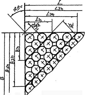
for: 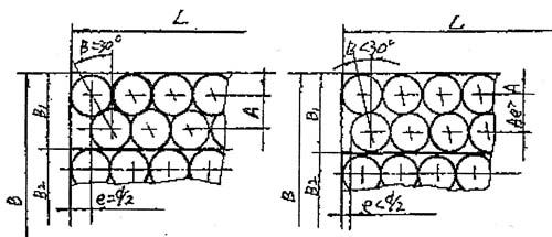
Guangzhou Athena Cosmetics Manufacturing Co.,Ltd is a subsidiary of YALAN international group which is located in Guangzhou,china.it is the production center of YALAN international group branding products,specialized in the development and production if cosmetics.ATHENA is qualified for import and export.
controls the quality in full accordance with GMP, ISO9001 quality system good manufacturing practice for cosmetics and key points of cosmetic production licence inspection.
Cutting and calculation of circular blank layout plate (2)